The 427 FE engine is still a popular engine among Ford enthusiasts, some 40 years after winning Lemans.
427 SOHC "Cammer"
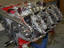

SOHC engine showing cam, rockers and timing chains
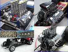
Examples of racing 427 SOHC's
The Ford Single Overhead Cam (SOHC) 427 V8 engine, familiarly known as the "Cammer" was released in 1964 to maintain NASCAR dominance and to counter the Chrysler 426 Hemi engine. The Chrysler 426 used an extremely large block casting that dwarfed the earlier 392 Hemi. The Ford 427 block was closer dimensionally to the early Hemis than to the elephantine 426 Hemi: the Ford FE bore spacing was 4.63 in (117.6 mm) compared to the Chrysler 392's bore spacing of 4.5625 in (115.9 mm).
The Ford FE's deck height of 10.17 in (258.3 mm) was lower than that of the Chrysler 392 at 10.87 in (276.1 mm). For comparison, the 426 Hemi has a deck height of 10.72 in (272.3 mm) and bore spacing of 4.8 in (121.9 mm); both Chrysler Hemis have decks more than 0.5 in (12.7 mm) taller than the FE.
The engine was based on the high performance 427 side-oiler block, providing race-proven durability. The block and associated parts were largely unchanged, the main difference being use of an idler shaft instead of the camshaft in the block, which necessitated plugging the remaining camshaft bearing oiling holes.
The heads were newly-designed cast iron items with hemispherical combustion chambers and a single overhead camshaft over each head, operating shaft-mounted roller rocker arms. The valvetrain consisted of valves larger than those on Ford wedge head engines, made out of stainless steel and with sodium-filled exhaust valves to prevent the valve heads from burning, and dual valve springs. This design allowed for high volumetric efficiency at high engine speed.
The idler shaft in the block in place of the camshaft was driven by the timing chain and drove the distributor and oil pump in conventional fashion. An additional sprocket on this shaft drove a second timing chain, 6 ft (1.8 m) long, which drove both overhead camshafts. The length of this chain made precision timing of the camshafts an issue to be considered at high rpms.
The engine also had a dual-point distributor with a transistorized ignition amplifier system, running 12 amps of current through a high-output ignition coil.
The engines were essentially hand-built with racing in mind. Combustion chambers were fully machined to reduce variability. Nevertheless, Ford recommended blueprinting the engines before use in racing applications. With a single four-barrel carburetor they were rated at 616 horsepower (459 kW) at 7,000 rpm & 515 lb·ft (698 N·m) of torque @ 3,800 rpm, and while equipped with dual four-barrel carburetors they made 657 horsepower (490 kW) at 7,500 rpm & 575 lb·ft (780 N·m) of torque @ 4,200 rpm. Ford sold them via the parts counter, the single four-barrel model as part C6AE-6007-363S, the dual carburetor model as part C6AE-6007-359J for $2350.00 (as of October, 1968). Weight of the engine was 680 lb (308 kg).
For more info and photos, go here: Click
|
FE engine displacements |
Displacement |
Bore |
Stroke |
332 cu in (5.4 L) |
4.000 in (101.6 mm) |
3.300 in (83.8 mm) |
352 cu in (5.8 L) |
4.002 in (101.7 mm) |
3.500 in (88.9 mm) |
360 cu in (5.9 L) |
4.052 in (102.9 mm) |
3.500 in (88.9 mm) |
361 cu in (5.9 L) |
4.047 in (102.8 mm) |
3.500 in (88.9 mm) |
390 cu in (6.4 L) |
4.052 in (102.9 mm) |
3.784 in (96.1 mm) |
391 cu in (6.4 L) |
4.052 in (102.9 mm) |
3.784 in (96.1 mm) |
406 cu in (6.7 L) |
4.130 in (104.9 mm) |
3.784 in (96.1 mm) |
410 cu in (6.7 L) |
4.054 in (103.0 mm) |
3.980 in (101.1 mm) |
427 cu in (7.0 L) |
4.232 in (107.5 mm) |
3.784 in (96.1 mm) |
428 cu in (7.0 L) |
4.132 in (105.0 mm) |
3.980 in (101.1 mm) |
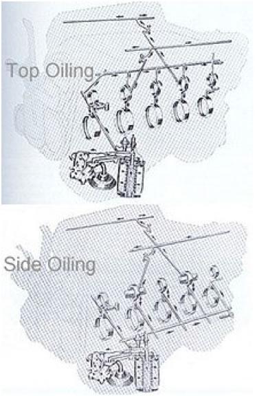
FE oil flow paths
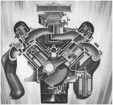
FE cutaway showing deep skirted block
The FE and FT engines are Y-block designs—so called because the cylinder block casting extends below the crankshaft centerline, giving great rigidity and support to the crankshaft's bearings. In these engines, the casting extends 3.625 in (92.1 mm) below the crankshaft centerline, which is more than an inch below the bottom of the crank journals.
All FE and FT engines have a bore spacing (distance between cylinder centers) of 4.63 in (118 mm), and a deck height (distance from crank center to top of block) of 10.17 in (258 mm). The main journal (crankshaft bearing) diameter is 2.749 in (69.8 mm).
Blocks were cast in two major groups: top-oiler and side-oiler. The top-oiler block sent oil to the top center first, the side-oiler block sent oil along a passage located on the lower side of the block first.
Because the FE was never a completely static design and was constantly being improved by Ford, references to a particular version of the FE can become difficult. Generally though, most FE's can be described using the following descriptors:
1) Carburetor count, i.e. single 2V (2 barrel), single 4V, dual quad (2 4V carburetors), tripower (3 2V carburetors) or weber (4 2V weber carburetors).
2) Top-oiler or Side-oiler block (though there are known instances of side-oiler blocks drilled at the factory as top-oilers; perhaps to salvage blocks with quality control issues that prevented them from being completed as side-oilers).
3) Head type: low-riser, medium-riser, high-riser, tunnelport, or SOHC. These descriptions actually refer mostly to the intakes used with the heads...a low-riser intake, designed to fit under a low hoodline was the earliest design. The high-riser intake required a bubble in the hood of cars it was installed in for clearance. While the low and medium riser heads could be used in combination with either low or medium riser intakes, the high riser head required a high-riser intake due to the increased height of the intake port. The medium riser's intake port is actually shorter in height, though wider, than the low-riser's port. The high-riser's ports are taller than either the low or medium-riser ports. Low-riser intakes have the carburetor placed relatively low so that the air-fuel mix must follow a more convoluted path to the chamber. A high-riser's intake places the carburetor approximately 6 in (152 mm) higher so the air-fuel mixture has a straighter path to the chamber. The tunnelport and SOHC heads both bolted onto FE blocks of either variety but required their own matching intakes. Within the major head groups, there were also differences in chamber designs, with small chambers, machined chambers and large chambers. The size and type of chamber affected the compression ratio, as well as the overall performance characteristics of the engine.
|

